
By Dr James Park
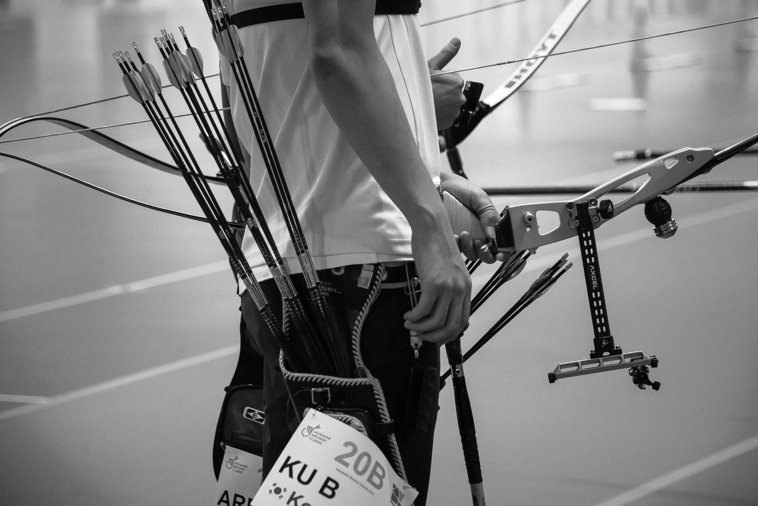
In my recent article “Tips on optimising your field archery gear” in Bow 156, I noted that while I use X10s with my recurve bow on the target range, I use ACEs on the field course. The ACEs have less mass than the X10s and hence a higher initial speed.
At the longest distances on the field course (60m) their speed is still greater than for the X10s, although the X10s overtake them at very long distances. That means that my sight settings are closer together for the ACEs than for the X10s and hence I have more tolerance in dealing with distance estimation errors and slopes. The ACEs, while having a larger diameter than the X10s, still have a reasonably small diameter and are hence still quite good when it is windy.
Prior to buying my ACEs, I modelled their behaviour during the power stroke of my recurve bow. I wanted arrows that had the least mass and for which I would be able to use the same draw force, and changing, at most, the pressure button. In this article I will show how I model the arrows. In a later one, I will show how I model their dynamic behaviour in the bow and down range.
An arrow shaft can be characterised by its outer diameter, stiffness and mass. In most cases it is usual for the shaft to be a round, hollow tube, as that facilitates fitting the point and nock. The arrow shaft stiffness is determined by the cross-sectional shape and the shaft material (or materials). The mass is determined by the volume of each material.
Most arrow shafts are now constructed using carbon fibre reinforced plastic. For arrows such as the X10 and ACE, the carbon fibres are oriented longitudinally along the arrow shaft. For others there are also fibres angled to the shaft’s longitudinal axis. The carbon fibres are held in place by an epoxy resin (the matrix), although the matrix does not provide significant strength compared to the carbon.
Some arrow shafts, such as the X10 and ACE, also have an aluminium inner shaft. I prefer that, as the aluminium provides a good gluing surface for arrow points and additional circumferential strength to resist longitudinal splitting. However, the carbon fibres dominate the shaft’s stiffness.
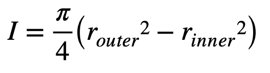
The arrow shaft can be modelled as an inextensible – that is, fixed length – flexible beam. Since we are only dealing with small amplitudes of flexing, we can use the Euler-Bernoulli beam equation. For a beam supported at each end and a load in the centre, as in an arrow spine test, the deflection of the centre of the beam is given by:
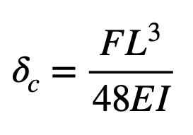
Where:
- F is the force acting at the centre of the beam
- L is the length of the beam between the supports
- E is the modulus of elasticity of the beam’s material
- I is the area moment of inertia of the beam’s cross section
Note that the deflection depends on the cube of the length, hence it is very sensitive to that parameter.
Given that formula, it is quite simple to calculate the deflection in a spine test for an arrow made from a single material and with uniform cross section along its whole length. It is significantly more challenging for arrow shafts with varying cross section and multiple materials. To do that, I consider the arrow to be constructed using many short sections, each of which has a constant cross section.
Arrow manufacturers provide us with a small amount of data about the shafts. Typically, we get the mass per unit length, the outside diameter and the spine. The data sheets usually do not include the modulus of elasticity nor the area moment of inertia.
However, in modelling an arrow, we need to know parameters such as the outside diameter and mass per unit length more accurately than provided in the data sheet. I first calculate the area moment of inertia of the arrow shaft. To do that, I use a Vernier caliper to measure the shaft’s outside diameter along its length.
I want that measurement to an accuracy of at least 0.01mm. I also need the inside diameter, which is usually constant, but which is more challenging to measure accurately. If the shaft has carbon and aluminium, I need measurements for both.
Usefully, for shafts such as the X10 or ACE, the inside and outside diameters for the aluminium inner tube are well defined.
The area moment of inertia for each component is given by:
Once you have the area moment of inertia along the shaft, you can guess the modulus of elasticity for each material – easy for the aluminium of EI along the shaft. You can also guess the density of each component and calculate the mass per unit length.
For a shaft with uniform cross section along its length, we can then use the formula above to run a mathematical spine test. If our measurements of the diameters are accurate and we have guessed the correct modulus
of elasticity, the calculated deflection should match the spine as stated by the manufacturer.
Similarly, our calculated mass per unit length should be reasonably close to the manufacturer’s specification. If they do not match, refine the estimates of the modulus of elasticity and density, and try again.
A type of arrow shaft is usually available in various stiffnesses (spines). Usually, for carbon shafts, several spines
are made with the same internal diameter but different external diameters – the stiffer shafts have larger diameters. Usually, but not in all cases, the same carbon is used in shafts of different spine. That is, the material in those shafts should have the same modulus of elasticity but different area moments of inertia. This can be used to advantage to refine our modelling.
We can model a number of different spine sizes for the same type of arrow shaft, knowing that the modulus of elasticity and material density should be the same for each and that the shaft outside diameters and masses per unit length should be close to the maker’s data sheet. We can use that to refine our estimates of the shaft outside diameters.
That whole process is reasonably easy to implement for simple arrow shafts – you can do it quite nicely on a simple Excel spreadsheet. It is substantially more complex for arrow shafts with varying outside diameter – such as the X10 or ACE – or for those with constant outside diameter but with varying modulus of elasticity along the shaft, such as some Carbon Express arrow shafts.
To model those more complex shafts, I use a mathematical ‘dynamic spine test’. There is more mathematics involved than would be appropriate for an article such as this, but in essence, I model the arrow in many small sections along its length, bend it to the required deflection between two supports with the spine test force on it, let it go and see if it sits there or moves.
If it, mathematically speaking, sits there, everything is correct; but if it moves it means some parameter is not correct. This could be that I have the wrong modulus of elasticity, or diameter.
I have modelled most Easton arrow shafts for example, I have modelled the full range of X10, ProTour, ACE, X7, Carbon One and others – together with an assortment of arrow shafts from other manufacturers.
Now that I have the various arrow shafts modelled (very accurately), I can then (mathematically) add points, fletching and nocks and model their behaviour both during the bow’s power stroke then in free flight. For example, with my recurve bow, I had a set of X10s, size 600, which I knew worked well.
My modelling of their dynamic behaviour matched their actual behaviour. I could then swap them out for ACEs in the model and select the spine size, point mass, nock and fletch type, to get the ACEs behaving well with the same draw force.
Having done the modelling, I bought the shafts and they did indeed do what I wanted. My modelling showed me that I could use either a 620 or a 670 ACE, with different point masses – I selected the 670 as that gave me the lowest overall mass and the tightest sight settings. And this was the initial objective.
Dr. Park, I appreciated your article and was wondering if you are considering or would consider making your X10 ACE behavior model available as a fill-in the blanks app?
Regards
Buzz Hooker